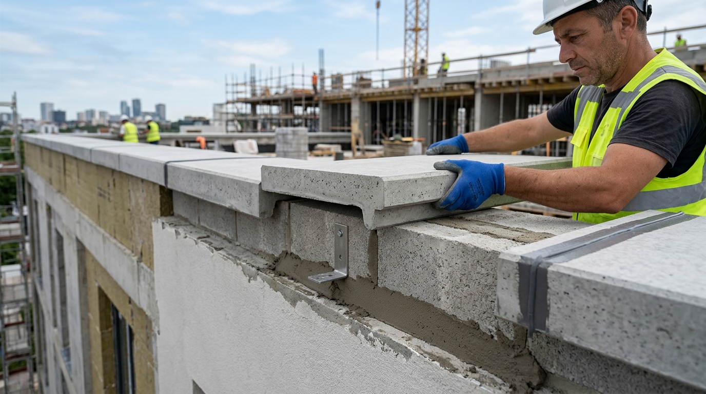
Precast wall coping serves as the primary defensive cap for parapets, boundary walls, and retaining structures. Designed to shed rainwater away from building facades, high-grade precast concrete coping prevents water ingress, efflorescence, freeze-thaw spalling, and gradual structural decay. Achieving reliable protection requires strict adherence to architectural detailing—specifically slope geometry, drip grooves, mechanical anchor placement, and high-performance joint sealant application. Utilizing engineered precast coping solutions ensures exact dimensional tolerances and superior material density, establishing an impermeable barrier against extreme environmental conditions.
Technical Section Details of Precast Wall Coping
Proper architectural detailing of precast concrete wall caps balances aesthetic integration with fluid dynamics. Coping elements must be engineered to handle rain load without allowing runoff to stream down the exposed face of the masonry or cladding below.
- Cross-Sectional Slope: A minimum cross fall slope of 1:40 (or approximately 1.5 to 2 degrees) is required. Coping units can be single-sloped (mono-pitch) for outward watershedding or double-sloped (duo-pitch) to shed water equally to both sides.
- Overhang Clearance: Coping profiles must extend beyond the finished wall face by a minimum of 30 to 50 mm on each side. This projection prevents water dripping directly onto the wall surface.
- Drip Grooves (Drip Edges): Continuous drip grooves located on the underside of the overhang break the surface tension of water. The standard detail requires a recess of at least 10 mm wide by 10 mm deep, positioned no less than 15 to 20 mm back from the outer edge.
- Unit Length and Expansion Gaps: Precast coping segments are typically manufactured in standard lengths between 600 mm and 1200 mm to minimize handling weight while maintaining joint integrity with 6 mm to 10 mm movement joints.
Step-by-Step Installation Techniques for Precast Coping
Executing precast coping installation demands rigorous surface preparation and systematic alignment. Mechanical anchoring and bed placement must work in tandem to withstand wind uplift and thermal movement.
1. Substrate Preparation and Leveling
The top surface of the masonry or concrete parapet wall must be thoroughly cleaned, free of dust, laitance, oil, and loose debris. Dampen the substrate prior to applying bedding mortar to prevent premature moisture loss from the mix. Check the elevation line using laser levels to establish a consistent reference datum across the entire run.
2. Bedding Layer Application
Apply a continuous bed of polymer-modified high-strength cementitious mortar, maintaining a consistent thickness between 10 mm and 15 mm. Spot bedding (dot-and-dab) must be strictly avoided as it creates hollow voids beneath the coping stone where trapped moisture can freeze, expand, and fracture the concrete assembly.
3. Mechanical Anchoring and Dowel Fixings
For high-rise structures, parapet walls subjected to high wind loads, or coping units set on inclined surfaces, mechanical anchorage is mandatory. Stainless steel pins or dowels (Grade 304 or 316) are cast into the underside of the precast unit or set into pre-drilled holes using structural epoxy resin. These anchors interlock directly into drilled holes within the supporting wall substrate.
Joint Sealing and Thermal Expansion Management
Precast concrete coping units undergo thermal expansion and contraction cycles. Incorrectly sealed joints lead to water penetration, efflorescence, and joint failure over time. Referring to established outdoor surface application and joint filling guidelines ensures thermal movements are accommodated without compromising seal integrity.
- Joint Preparation: Ensure joint side walls are completely dry, clean, and primed according to sealant manufacturer specifications. Mask outer edges to preserve clean aesthetic lines.
- Backer Rod Placement: Insert a closed-cell polyethylene backer rod into the joint space. The backer rod establishes proper sealant depth (typically a 2:1 width-to-depth ratio) and prevents three-sided adhesion, allowing the sealant to flex freely.
- Sealant Selection: Apply a high-modulus polyurethane or structural silicone sealant designed for exterior concrete movement joints. Tool the sealant flush or slightly concave to allow smooth water runoff.
Integrating Waterproof Membranes Beneath Coping Units
The precast coping layer should never act as the sole barrier against moisture. A continuous flexible waterproofing membrane—such as a modified bitumen sheet or elastomeric liquid membrane—must run beneath the mortar bed across the full width of the wall top. This secondary barrier should lap over the exterior vertical cavity flashing, ensuring any moisture penetrating mortar joints drains safely outward without entering the cavity wall construction.
Material Specifications and Structural Compliance
High-performance precast coping units are manufactured under controlled factory conditions using dense concrete matrices, frequently reinforced with micro-synthetic or alkali-resistant glass fibers to prevent micro-cracking. Reviewing certified technical documents and structural specs ensures specified units meet required compressive strength (typically C35/45 or higher), low water absorption (<5%), and high freeze-thaw resistance thresholds defined by regional building codes.
Frequently Asked Questions
Why are drip grooves necessary on precast wall coping?
Drip grooves break the capillary action of water flowing under the overhang of the coping unit. Without a drip groove, rainwater travels around the edge and down the wall face, leading to staining, damp patches, and premature masonry degradation.
Can precast coping be installed using flexible adhesive instead of mortar?
Polymer-modified flexible tile adhesives or structural cementitious adhesives can be used on low-height walls or smooth concrete surfaces. However, traditional polymer-modified bedding mortar remains preferred for leveling uneven wall bases and providing structural support for heavier precast units.
How far should precast coping overhang the wall edge?
Standard architectural guidelines recommend a minimum overhang of 30 mm to 50 mm beyond the finished cladding surface. This distance allows space for an effective drip groove while shielding the wall interface from direct rainfall.
Selecting the Right Precast Coping System for Your Project
Achieving a durable wall coping installation relies on pairing precise architectural design with high-density precast components. Factors such as wall thickness, wind load exposure, facade material, and climate severity dictate whether custom profiles, single-pitch, or double-pitch coping modules are required. For tailored technical guidance, detailed CAD profiles, or project-specific manufacturing capabilities, contact Topaz Precast specialists to evaluate your structural requirements.