
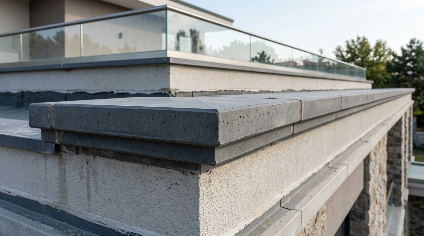
Outdoor precast wall coping details define the technical and structural standards used to top boundary walls, roof parapets, retaining walls, and architectural barriers. Functioning as a continuous protective cap, precast coping shields underlying masonry and concrete structures from rain, snow, and freeze-thaw damage while providing a clean architectural finish. Engineered with precision slope geometry and integrated drip grooves, modern precast coping elements prevent surface water from running down exposed exterior walls, significantly reducing dampness, efflorescence, and long-term material degradation.
Essential Structural Functions of Outdoor Precast Wall Coping
Parapet walls and perimeter fencing are among the most exposed elements of any building structure. Without adequate top protection, water easily penetrates vertical mortar joints, micro-cracks, and concrete voids. During cold weather, trapped moisture freezes, expands, and causes spalling or severe structural cracking.
Specifying precast concrete coping units solves these vulnerability points through several distinct mechanical and physical mechanisms:
- Controlled Water Shedding: Sloped top surfaces direct bulk rainwater away from the core masonry into drainage channels or exterior clear zones.
- Sub-Wall Shielding: An overhang profile keeps falling rain from clinging to the wall face.
- Thermal Mass and Stability: High-density precast concrete provides a rigid, UV-stable surface capable of withstanding extreme temperature fluctuations without warping.
- Architectural Continuity: Precast coping seamlessly aligns with adjacent facade cladding, terrace surfaces, and urban hardscapes.
Critical Technical Details in Precast Coping Profiles
Achieving absolute moisture control and long-term stability requires careful attention to specific geometrical and mechanical details during the design and detailing phases.
1. Drip Edge (Drip Groove) Detailing
The drip groove (or drip edge) is a narrow channel recessed into the underside of the coping overhang. As rainwater runs down the sloped top and around the outer edge, surface tension carries liquid along the underside until it encounters the groove. The physical interruption forces water to break surface tension and drop directly to the ground, preventing it from reaching the wall surface beneath.
- Minimum Groove Distance: Placed at least 20 mm to 30 mm away from the finished wall face.
- Dimensions: Typically 10 mm wide by 10 mm deep to prevent capillary bridging.
2. Slope and Profile Geometries
Depending on the wall placement and drainage design, precast coping profiles are divided into three core geometry types:
- Once-Splayed (Single Pitch): Slopes in a single direction, ideal for roof parapets where water must drain inward toward interior roof gutters.
- Twice-Splayed (Double Pitch / Apex): Slopes down from a central high point toward both sides, optimal for freestanding boundary walls and perimeter barriers.
- Flat Profile with Internal Pitch: Appears visually horizontal from elevation views while maintaining a subtle 1.5° to 2° top gradient for subtle water displacement.
3. Anchorage and Mechanical Fixings
While low-rise boundary copings are often laid directly on full mortar beds, high-rise parapets and wind-exposed parapet walls require mechanical anchor systems. Stainless steel dowels, pin connectors, or continuous restraint brackets secure individual precast modules to the structural substrate, preventing uplift caused by wind shear and thermal movement.
Joint Design and Sealant Selection for Outdoor Applications
Precast wall coping runs consist of multiple individual precast units placed end-to-end. The interface between these units represents the most critical potential leakage pathway if not detailed correctly. Thermal expansion and structural settlement cause minute movements across these joints.
For optimal joint performance, consult proper outdoor surface application and joint filling practices. Key recommendations include:
- Joint Width: Design joint widths between 6 mm and 10 mm to accommodate thermal movement.
- Backer Rod Installation: Insert a closed-cell polyethylene backer rod into the joint cavity to control sealant depth and prevent three-sided adhesion.
- Elastomeric Sealants: Apply high-performance polyurethane or neutral-cure silicone sealants capable of +/- 25% joint movement.
- Drainage Cavity Clearance: Ensure joint sealant does not block continuous internal drainage paths or sub-coping flashing membranes.
Material Performance and Load-Bearing Specifications
Commercial precast wall coping must comply with strict physical performance criteria to endure vehicular vibrations, weather exposure, and foot traffic on accessible parapets. High-strength precast formulations ensure high density, minimal water absorption, and superior abrasion resistance.
Reviewing detailed metrics in our technical specification table helps engineers verify compliance with target project standards. Key parameters include:
- Compressive Strength: High-grade concrete mixes formulated to achieve high durability thresholds (e.g., C35/45 or higher equivalents).
- Water Absorption: Low capillary absorption (under 5% total water uptake) to eliminate freeze-thaw degradation.
- Dimensional Tolerances: Strict manufacturing tolerances ensuring clean sightlines along extended wall runs.
Installation Sequence and Quality Control Checklist
Proper installation ensures precast coping units perform to their full design lifecycle. Structural engineers and contractors should verify each phase of the installation sequence:
- Substrate Preparation: Verify that the underlying masonry or concrete wall top is structurally sound, level, clean, and free from loose debris or form oil.
- Damp-Proof Course (DPC): Install a continuous waterproof membrane or flexible DPC across the top of the wall before bedding mortar placement.
- Mortar Bedding: Apply a polymer-modified, frost-resistant cement mortar bed (10 mm to 15 mm thick) ensuring complete coverage without voids.
- Alignment & Leveling: Set precast coping units using laser lines or string lines to ensure uniform overhangs and exact drip edge clearance.
- Joint Completion: Clean unit edges thoroughly before installing backer rods and primary weatherproofing sealants.
Frequently Asked Questions About Outdoor Precast Wall Coping
How far should precast wall coping overhang the finished wall surface?
Precast coping units should extend a minimum of 30 mm to 50 mm beyond the finished outer wall face on each side. This provides sufficient width to incorporate a functional drip edge groove and ensures dripping water stays clear of textured wall cladding or render.
Is a damp-proof course (DPC) required under precast coping?
Yes. A continuous damp-proof course or elastomeric waterproofing membrane must always be installed underneath precast coping. Although high-density precast concrete resists water penetration, the waterproof membrane beneath serves as a secondary defense barrier against moisture migrating through mortar bedding or joint interfaces.
Can precast coping units be customized for curved or radius walls?
Absolute precision for curved parapets or non-standard corner angles is achieved through custom precast casting. Segmented radius units are molded with pre-calculated radii to maintain uniform joint widths and smooth geometric curves along the entire wall length.
Engineering Reliable Boundary Protection for Commercial Projects
Specifying precise outdoor precast wall coping details ensures long-term architectural integrity, minimal maintenance costs, and durable moisture protection across all commercial and institutional developments. Whether planning roof parapets, landscape retaining walls, or perimeter security boundaries, utilizing engineered precast components delivers consistent quality and rapid jobsite assembly.
For custom profile drawings, structural anchoring guidelines, or project-specific technical support, contact our technical engineering team at Topaz Precast to discuss your architectural requirements.